Gallery Homemade DC Electronic Load Hackaday.io
Step 1: Watch the Video! The video gives you all the information you need to make your own adjustable constant load. During the next steps though, I will present you some additional information. Ask Question Step 2: Order the Components! Here you can find a parts list with example seller (affiliate links): Aliexpress:

DIY electronic load Sponsor PCBWay
Special $2 for 10 PCBs(100*100mm): https://jlcpcb.com Previous video: https://youtu.be/SIo_Gv7K7FoConstant Current Load video: https://youtu.be/8uBcywBUTkwCo.
DIY Electronic LOAD 300 Watt schematic with Komitart LAY6.
December 29, 2023 Build Your Own Active Load 28 Comments by: Lewin Day February 11, 2020 When it comes to testing power supplies, it's useful to have a dummy load to put the gear through its.
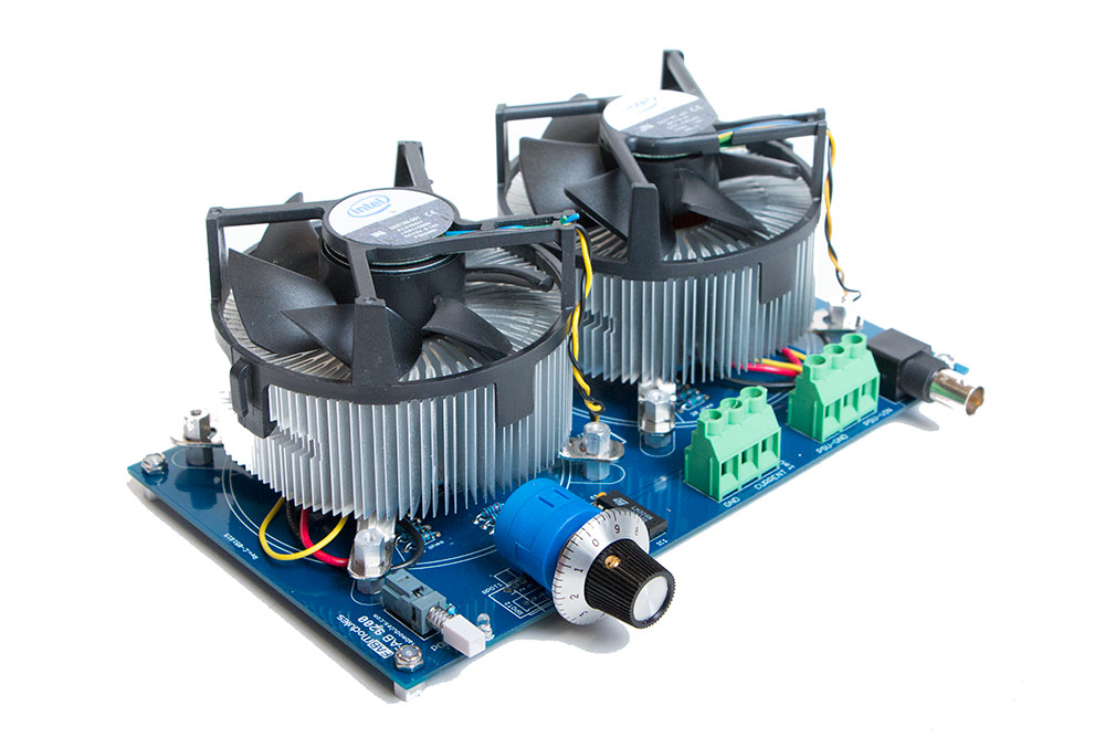
DIY Electronic Load PCB Kit for Testing Power Supplies FiveFish Audio
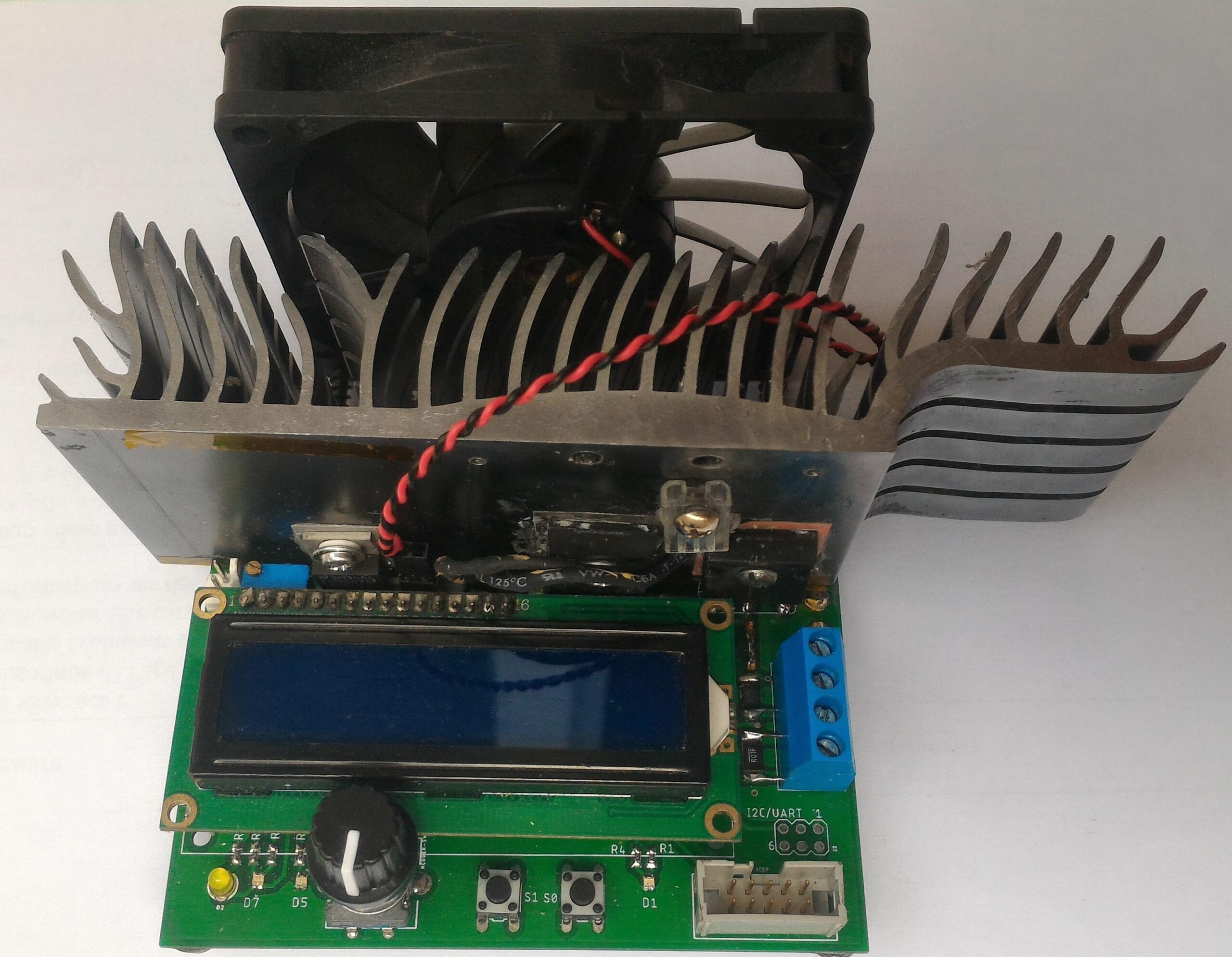
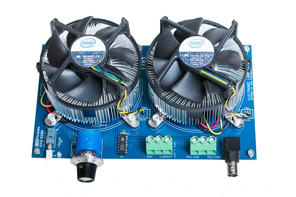
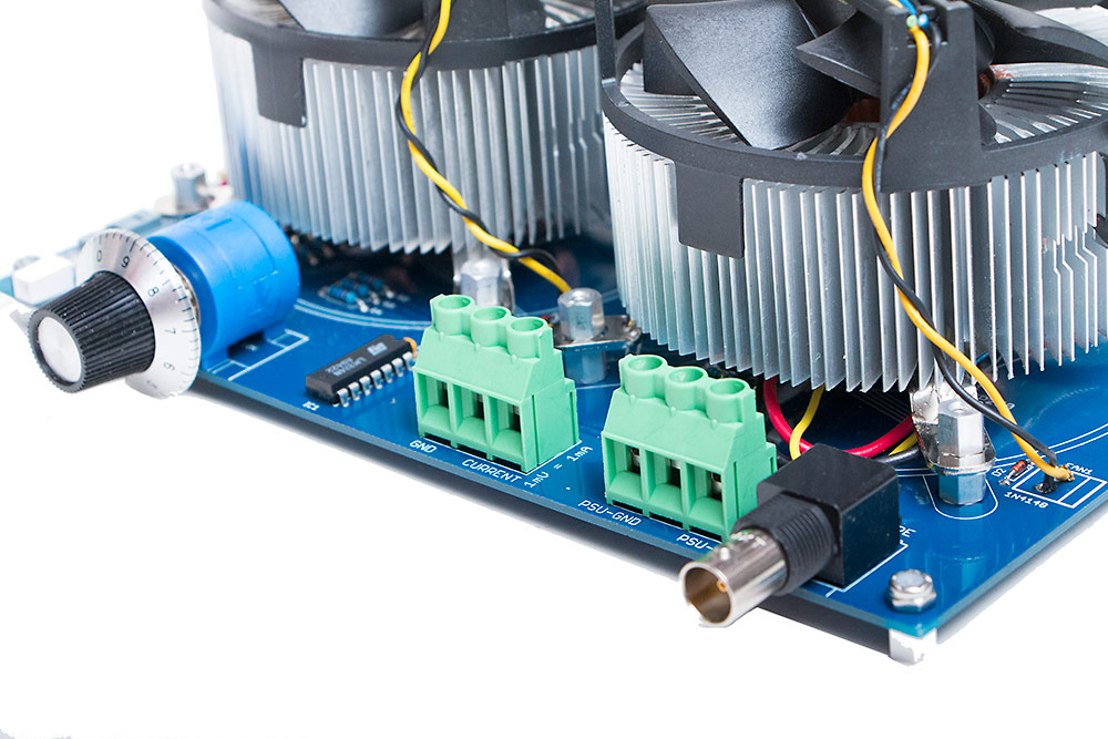
An encoder is used for current adjustment. By default, the current can be adjusted at a resolution of approximately 1mA/step. By pressing the encoder button, this resolution can be changed to 10mA/step and 100mA/step respectively. This makes it easier to to coarse adjustments. Constant power mode is achieved by calculating the desired set.
DIY ELECTRONIC LOAD 600 Watt schematic with Komitart LAY6.
By biasing the motor with a small DC voltage applied to one lead and reading the resulting voltage from the other, the knob's speed and direction can be detected, doing a serviceable job as rotary.
A DIY Electronic load for DCDC converter characterization
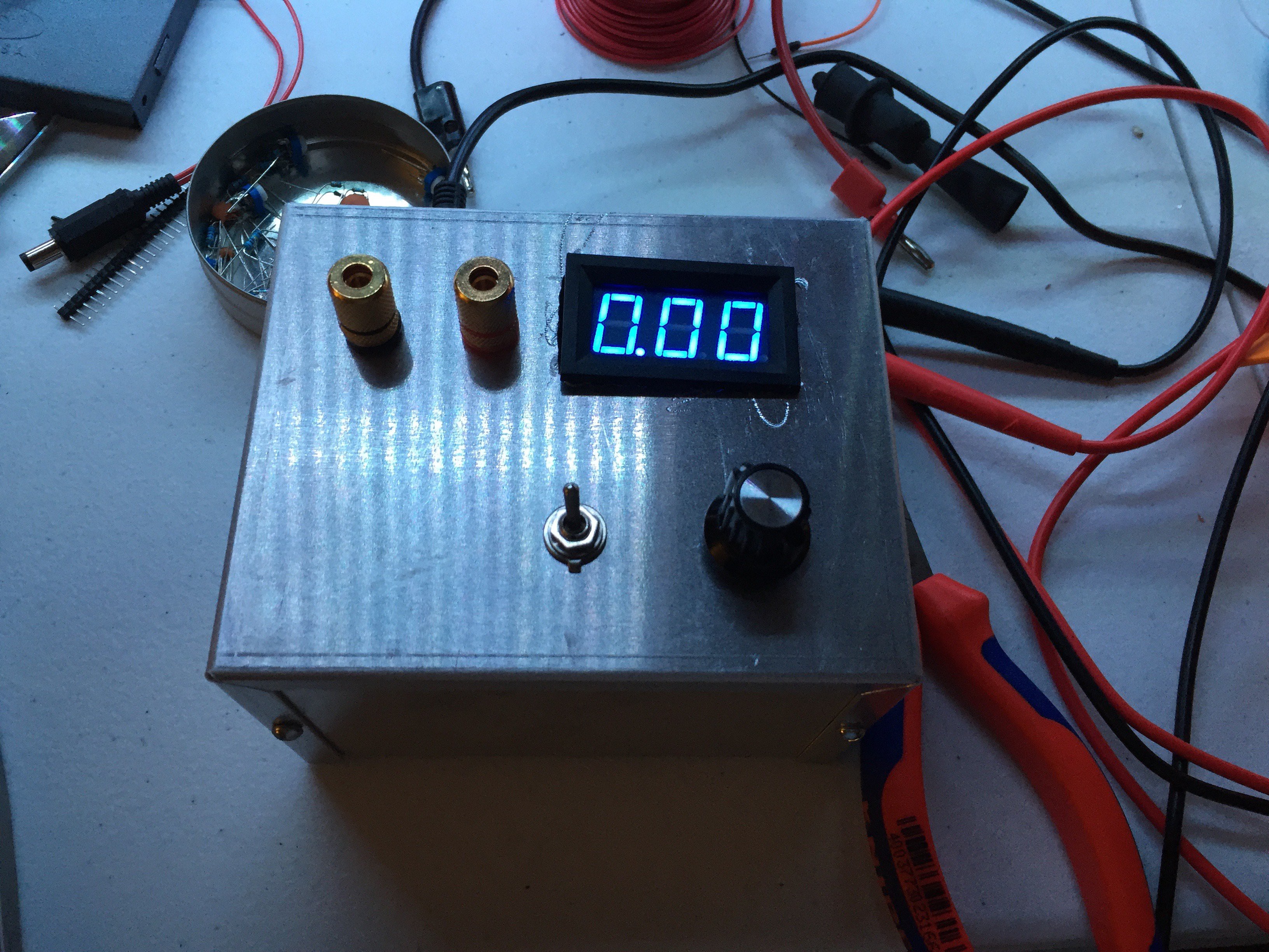
DIY Adjustable Electronic DC Load By voltlog in Circuits Electronics 22,947 104 2 Featured Download By voltlog Visit my website! Follow More by the author: About: Electronics enthusiast, vlogger on youtube. More About voltlog » In this project I am building an analog adjustable dc load with parts easily obtainable from ebay and banggood.
Spot This DIY Electronic Load’s Gracefully Hidden Hacks Hackaday
Electronic Load This repository hosts my work in developping a custom electronic load from scratch. For more information on what an electronic load does and what it can be used for, see this.

Homemade Digital Electronic Load Multiple Modes YouTube
In this tutorial, we will learn how to build our very own Adjustable Electronic Load using Arduino, which can take a maximum input voltage of 24V and drain current as high as 5A. For this project, we have used PCB boards which are manufactured by AllPCB, a china based professional PCB manufacturing and assembling service provider.
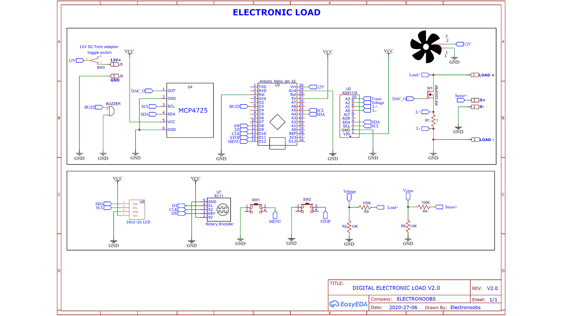
Arduino homemade electronic load schematic
EEVBLOG electronic load This project was created on 02/26/2019 and last updated 3 years ago. Description I needed an electronic load for testing DC-DC boost converters but didn't want to buy one (they're expensive!). I saw Dave Jones of the EEVBlog build a pretty handy looking electronic load very simply using a transistor current source.

DIY electronic load Sponsor PCBWay
With that out of the way, I would like to present my conceptual approach to the CC, CV and CR mode electronic load in an (IMO) elegant mostly analog circuit using 2 switches, 2 potentiometers and a bunch of resistors/caps. Feedback is appreciated.
DIY KIT Electronic LOAD schematic and Komitart LAY6.
Here are the lab's current electronic loads: Figure 2 Manually-adjustable electr (on)ic loads I could mount these in the supply chassis along with a fan. But it might be nice to have a true electronic load - something with a bit more functionality. Something that doesn't require a screwdriver to adjust. Something like:
DIY Electronic Load PCB Kit for Testing Power Supplies FiveFish Audio
April 29, 2014. Some projects are both educational and useful. We believe that [Jasper's] Arduino based electronic load is one of those project. [Jasper's] electronic load can not only act as.

DIY ELECTRONIC LOAD 600 Watt schematic with Komitart LAY6.
An electronic load, also known as a constant current dummy load, is a device design so a power supply can draw a certain amount of current without dissipating too much of heat. Basically, when you dial in a current level, the electronic load circuitry will draw only that amount of current, regardless of the voltage.
DIY Electronic Load PCB Kit for Testing Power Supplies FiveFish Audio
Figure 1: Schematic For 3A Load Box The opamp, an LT1635, also contains a buffered 200mV reference (U1a) which is amplified to obtain 3V. I trimmed the output current to 3A by adding 2MΩ across R6. If you want to make a fully adjustable load box, add a 1MΩ log taper pot or 10-turn 100kΩ pot between U1a and U1b.

ADJUSTABLE DIY ELECTRONIC LOAD YouTube
A DIY Electronic Load With A Twist 13 Comments by: Tom Nardi June 6, 2020 If you're testing a power supply or battery pack, an electronic load is a nice tool to have. By watching the voltage.

DIY DC Electronic Programmable Load 5 Steps Instructables
Click "Like" to get coupon: https://jlcpcb.com/Workshop-PCB-Project-Competiton$2/5pcs 2Layer & $5/5pcs 4Layer PCBs: https://jlcpcb.com🔥This is a second ver.